How to mess up a simple ThinkPad X230 BIOS flash and how to recover from it
Background
I have a Lenovo ThinkPad X230. It’s a small and good laptop that I’ve used as my main laptop and a server as well.
A couple of years ago I messed around with flashing alternative BIOS implementations on the X230, such as the skulls project, which made installing prebuilt coreboot images very simple. Of course, before doing any testing, I made backups of the stock BIOS implementation (ooh, foreshadowing!).
Skulls was nice, it booted fast, but changing the boot order likely required modifications and rebuilding the coreboot image (I wanted to set the mSATA SSD as the first bootable device). It was also not UEFI-compatible, which could have probably been solved with something like TianoCore, but I didn’t feel like messing with that too much. Eventually I flashed the original UEFI implementation back and went on with my life.
Then I stumbled upon the 1vyrain project project, which allows you to “jailbreak” your BIOS. This modification also enables a lot more bells and whistles in the BIOS under the Advanced menu option, plus it also gets rid of the WiFi adaptor whitelist that Lenovo has put in place, allowing you to now use any adaptor that’s compatible with the form factor.
The mod was very easy to install and had no issues, until I got myself a DDR3 SODIMM RAM kit. One of the sticks was not working properly, showing up with graphical glitches and failing a memtest run. To troubleshoot it, I decided to change the speed at which the memory runs from DDR3-1600 to DDR3-1333. It booted, and still had the issues.
Then I changed it to DDR3-1066.
Black screen. Uh-oh.
Initial troubleshooting
Thinking that this is just a simple issue that I could get fixed by clearing the BIOS settings and starting fresh, I looked up some basic instructions on doing so.
Things I tried:
- remove the battery (even if it is completely dead, like mine), and hold the power button for 60 seconds, then attach the battery and turn it on again.
- remove both the battery and disconnect the internal CMOS battery that sits under the palmrest and hold the power button for 60 seconds again.
- disconnect all the batteries and leave the laptop sitting on a shelf, then try again.
- try “the secret ThinkPad power button combo”:
… unplug the AC adapter and take out the battery. Then, you push the power button 10 times in a row at one second intervals. Next, you push and hold the power button for 30 seconds. Then you put the battery back in and push the power button… and she lives. The computer came back, good as ever.
After all of that, the laptop was still as good as dead. You could see the light turn on, the fan starts spinning, but nothing shows up on the screen. At that point I knew that the BIOS reflash was probably my only choice.
Flashing the BIOS
To fix the issue, I had to flash the BIOS externally. Luckily I still had the original BIOS backup images available.
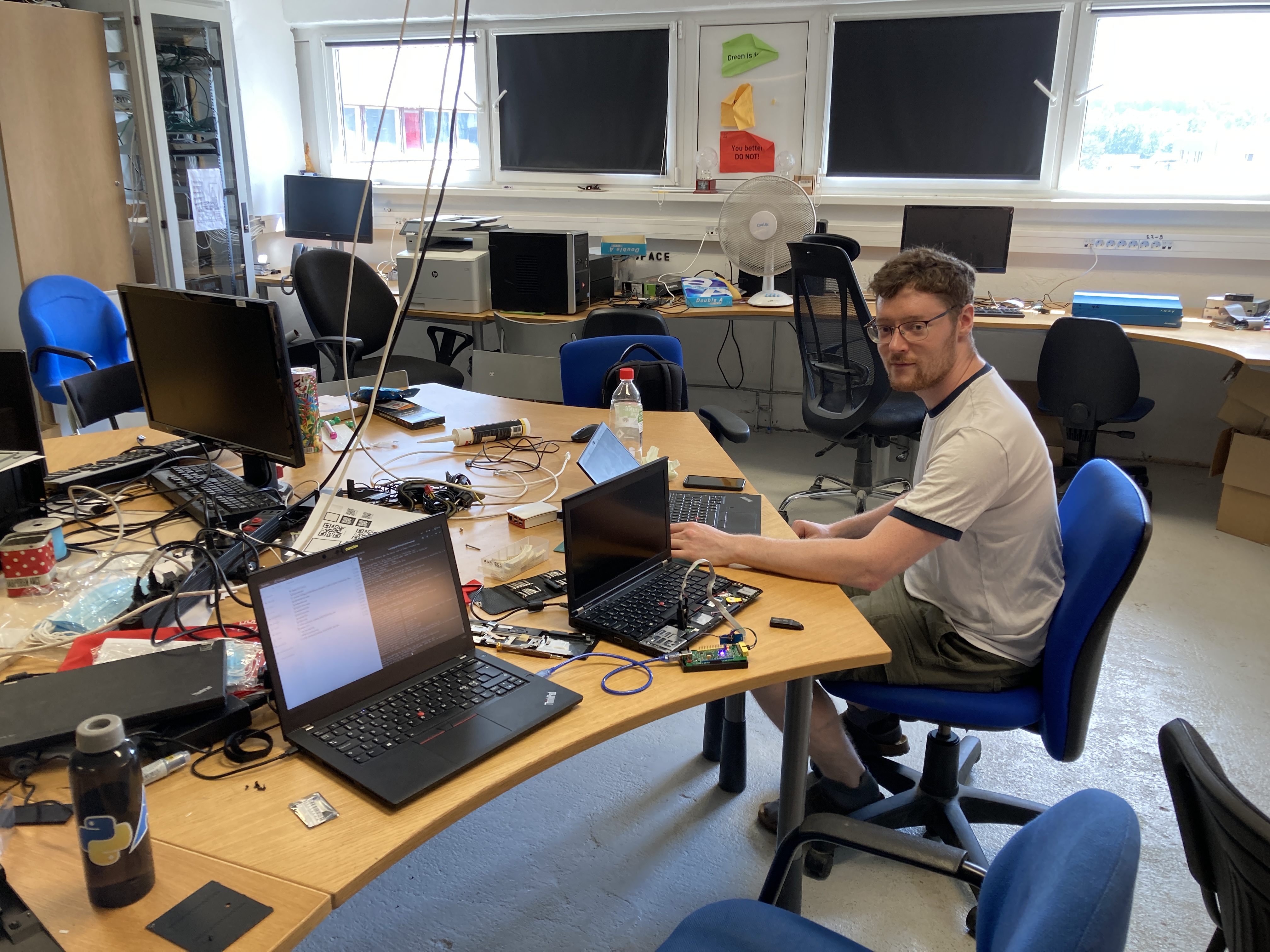
With the help of a good friend, we set everything up and did some tests to ensure that the connection is good and that read/write operations on the chips return consistent results.
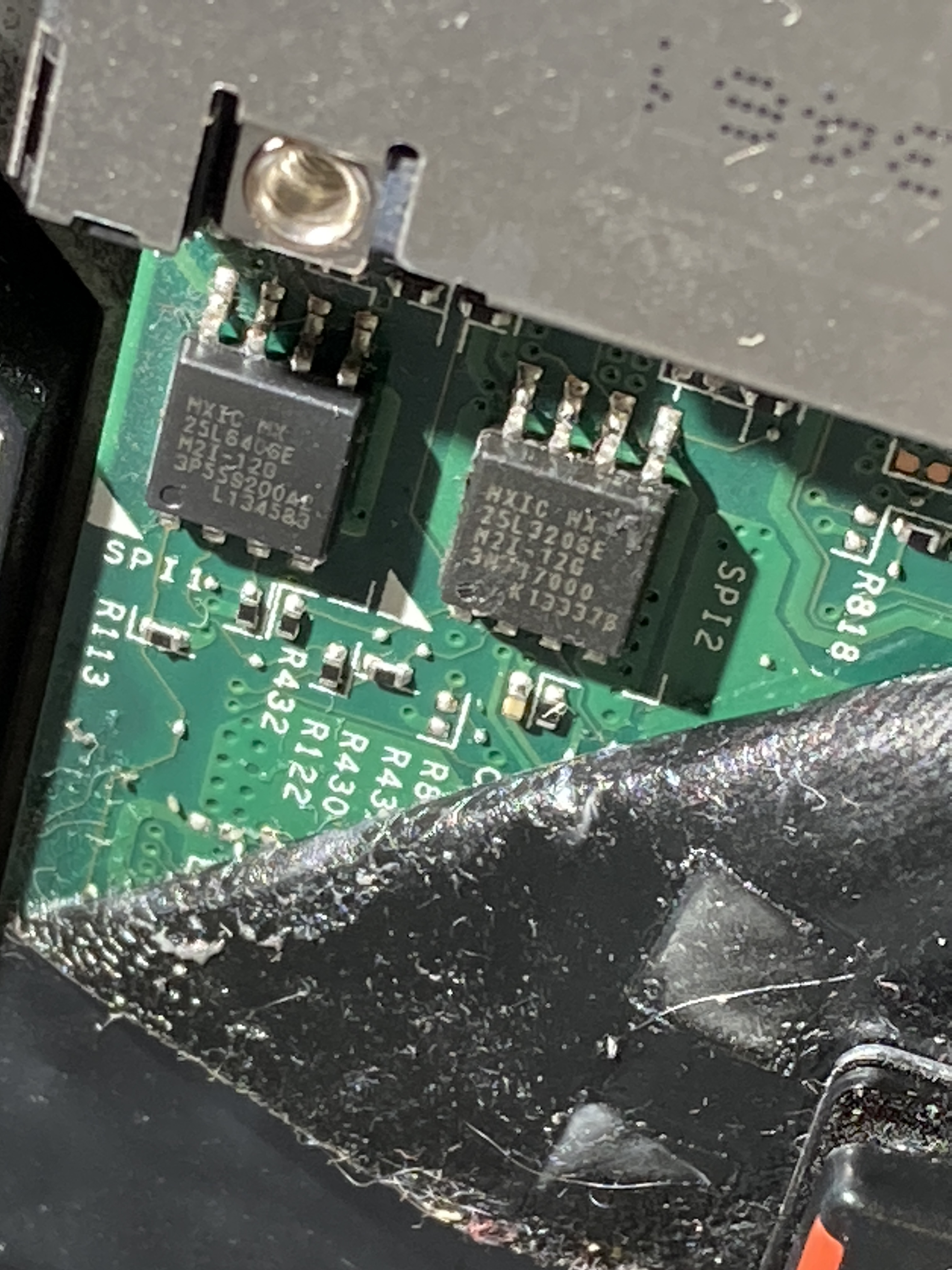
Once we had specified the correct chip type by looking at what was written on the chip package itself, we flashed both
the top and bottom chips with the original images that were once made as a backup. After reading the chips back and
comparing checksums using md5sum, it all looked good.
We disconnected the SOIC clip, attached the power cable and tried turning the laptop on. Power button light comes up for 1 second and then turns off. Not a good sign.
We flashed both chips again and made sure that everything is in order. No dice, the symptoms are the same.
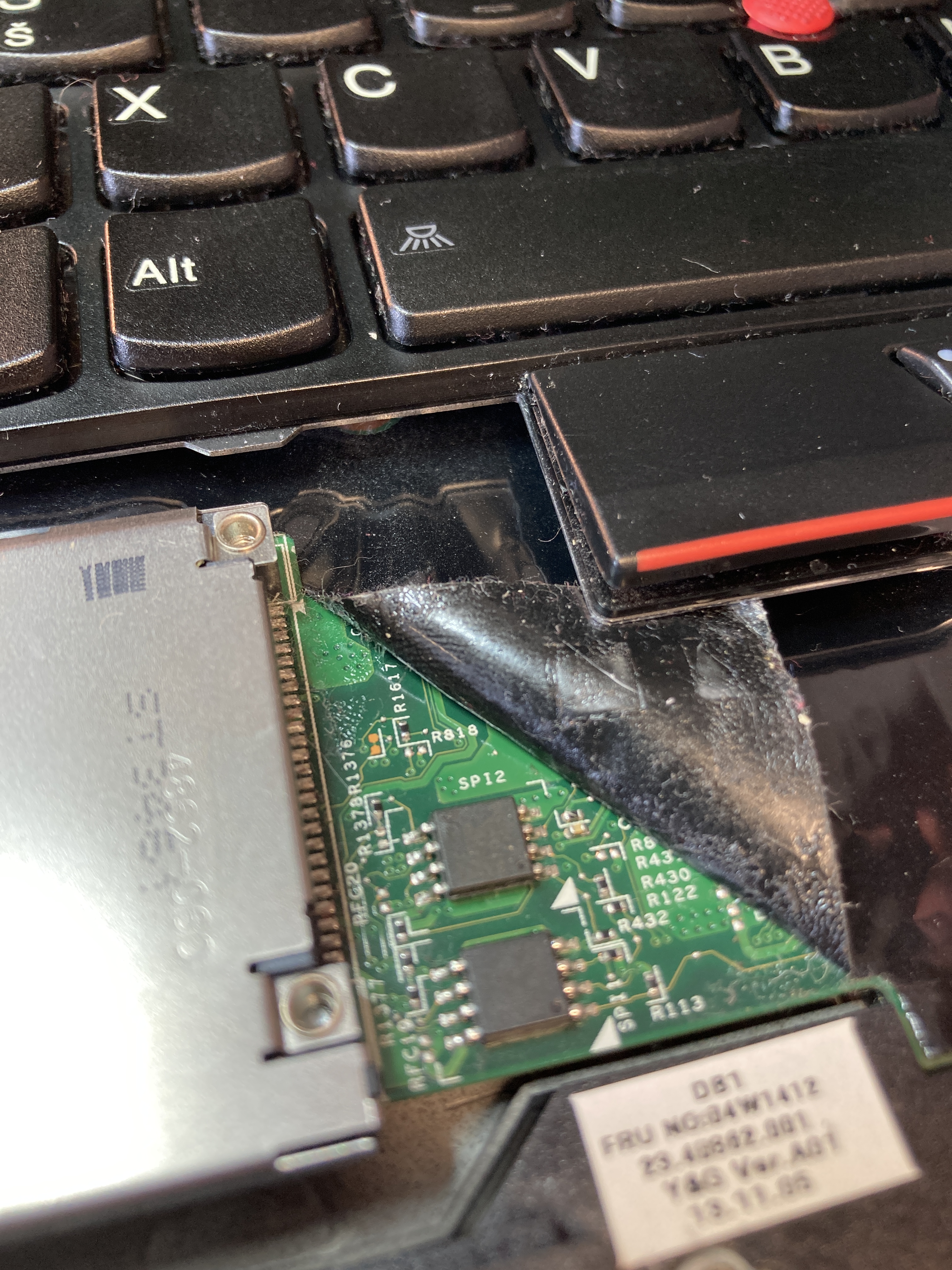
A closer look
It didn’t take too long for me to start thinking about what I could use all these extra laptop parts for. After all, the screen was good, it had 16GB DDR3 RAM, two SSD-s, a screen assembly in good condition etc. I was stopped in my tracks when my friend noticed something.
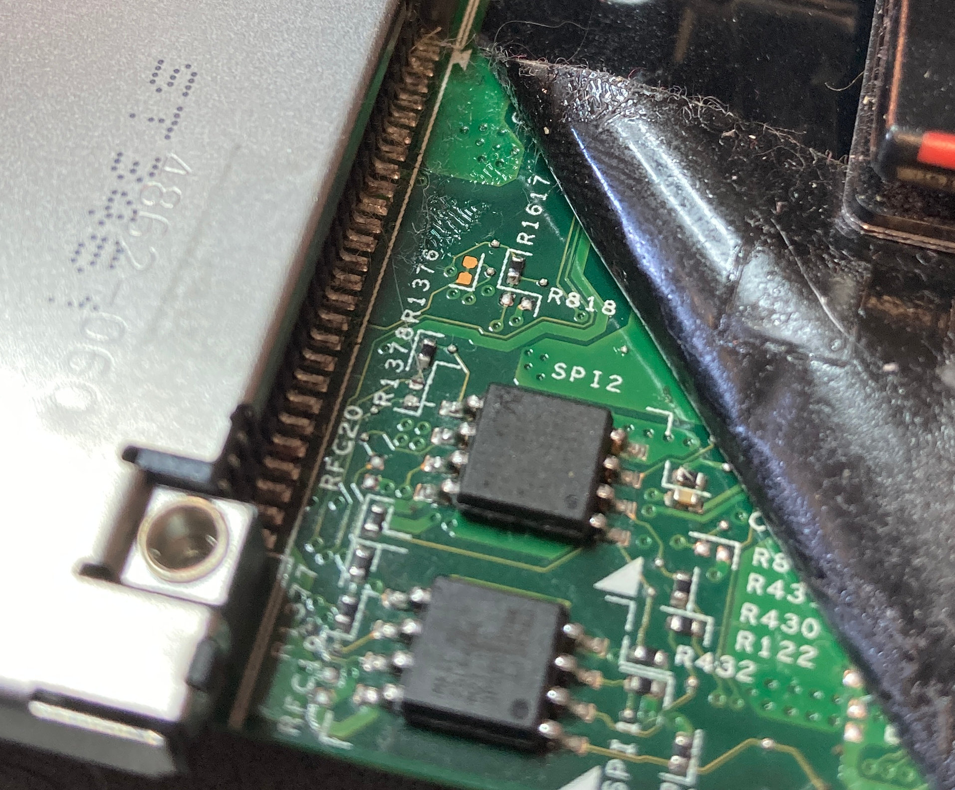
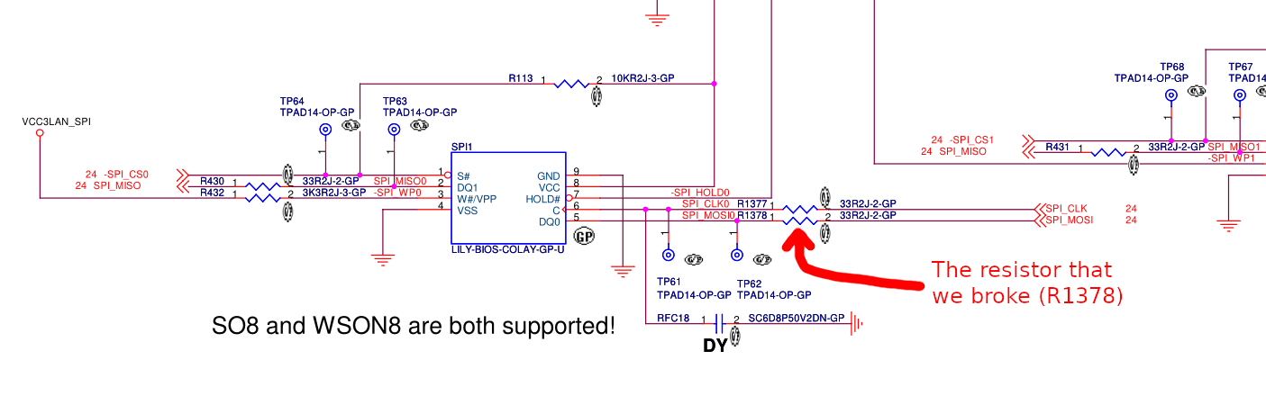
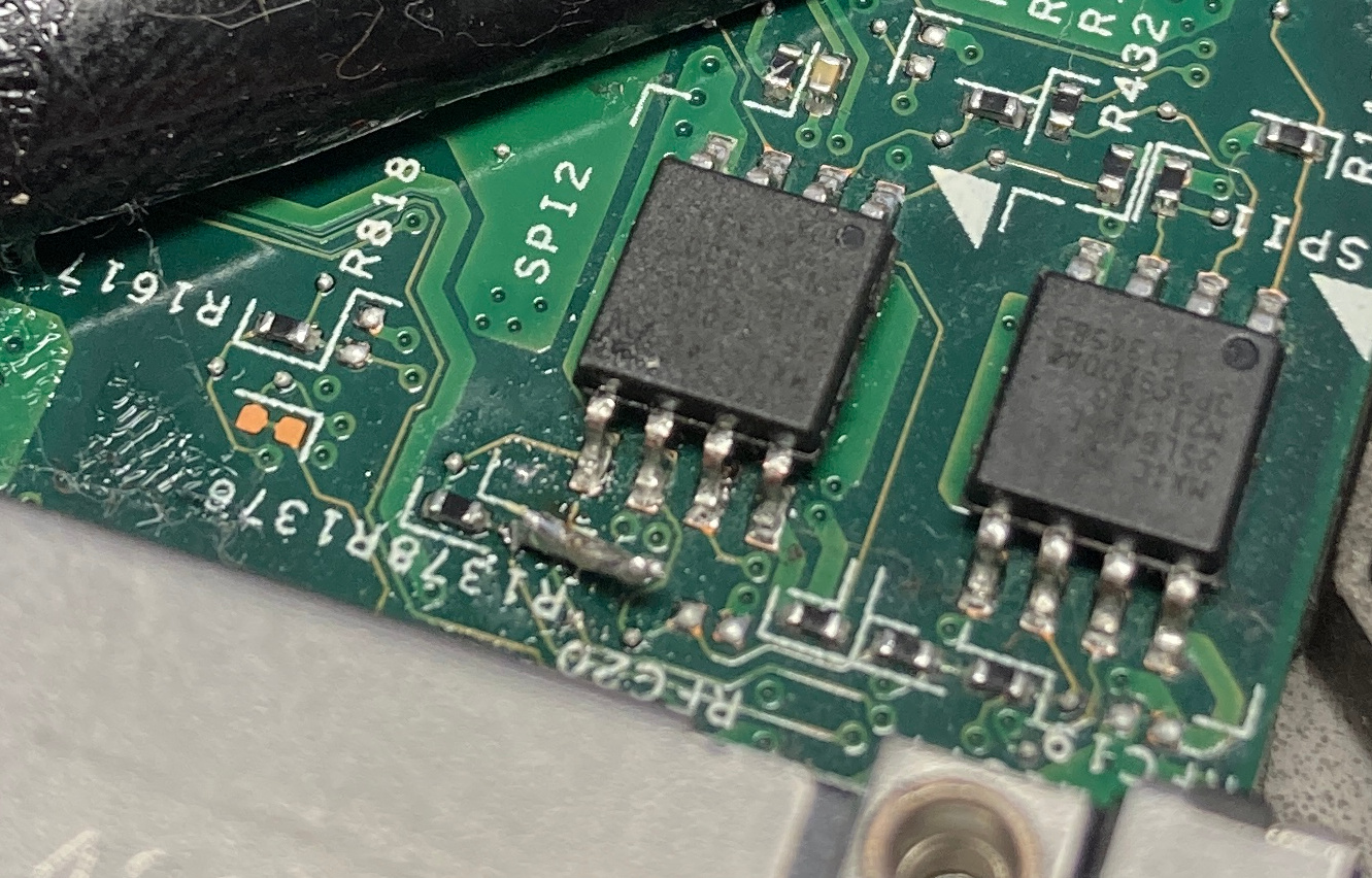
It turns out that during this flashing process, we (probably me) had managed to get rid of a resistor that sat next to the top flash chip. Whoops. Turns out that it was an important one, because over at Reddit, someone else also ran into this issue and had similar symptoms .
To resolve this, my friend had the idea of putting a 10K resistor in there to see if it fixes things. The issue was that the only one available right from the get-go was a very big one, so he had to be clever with it. He ended up positioning it upright with a piece of wire handling the other side.
This, however, didn’t improve the situation much.
Schematics to the rescue
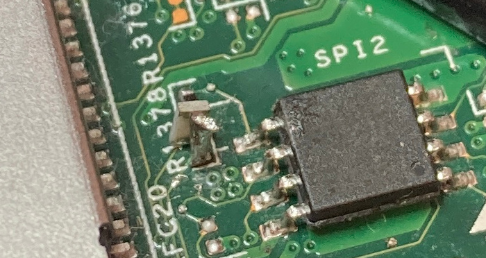
To understand the role of the missing resistor better, we started looking for schematics online. I managed to find an OK looking one from a random forum and started browsing through it. The keyword of the day was “SPI” and when searching for it, we found some promising results. My friend found the resistor and found that we could just short it, since the resistor used to be between two wires. And that he did.
We attempted to power on the machine again and this time the error sequence was different as the laptop went into some sort of a party mode with lights flashing. The usual troubleshooting steps didn’t work that well here, either, so it’s possible that the stock BIOS image did not like something here.
What we did have was the option of flashing the known-good skulls image on. I handled that part quite OK, since all the commands were in my bash history anyway. The excitement, however, got the best of me and I managed to repeat the original mistake and I bumped the soldered piece of wire off of the board, putting us back to the original issue.
After another session of carefully connecting the two wires, we repeated the steps and after the flash, we finally saw the Skulls splash screen.
It works!
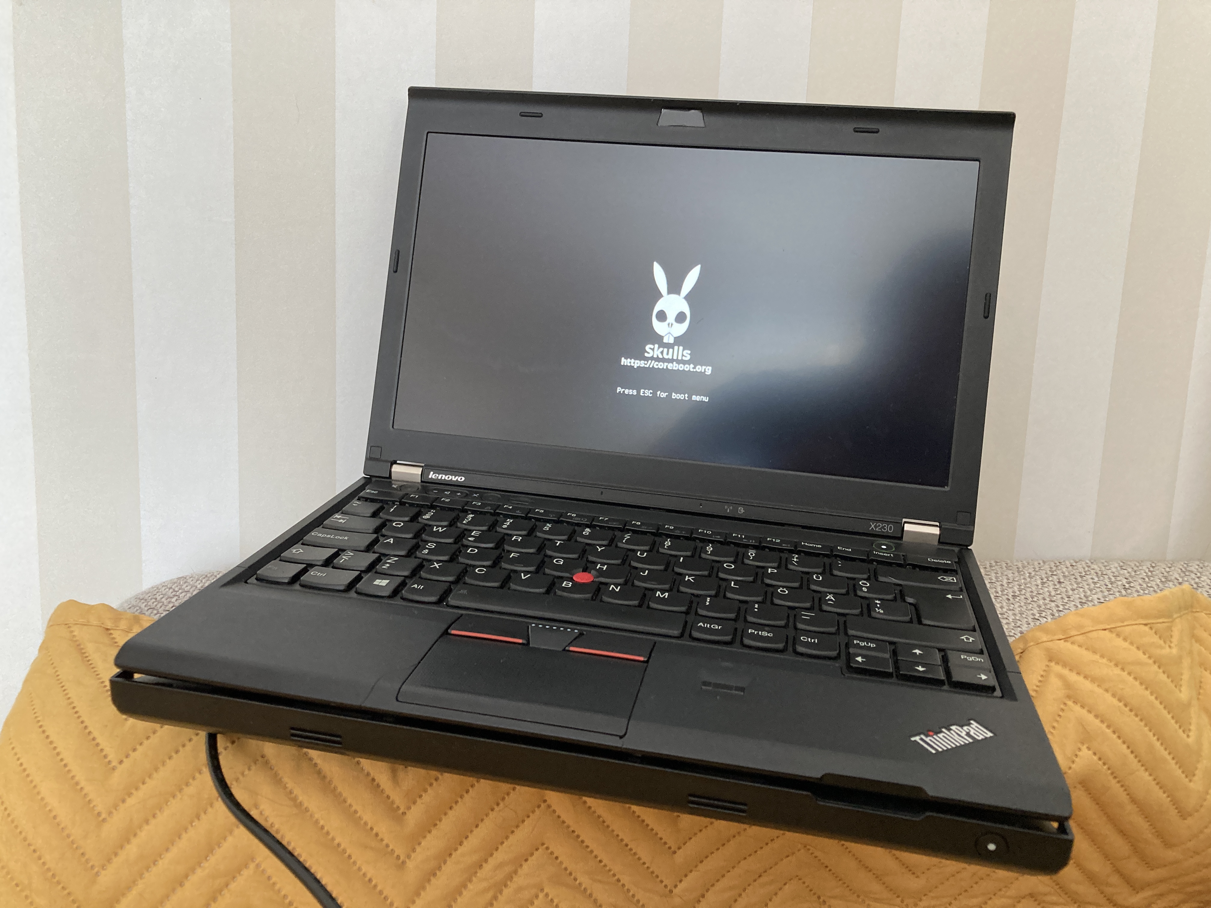
After booting into a Fedora 34 liveusb environment with iomem=relaxed, I grabbed the latest release of skulls (
released on 4/20 🔥) and used the internal flashing method to update.
Reboot, and we saw party mode again. Having used skulls in the past, I knew that this was likely down to skulls (or coreboot) being very picky about RAM. The solution here is to reseat the RAM modules and turn it on again. Why does that work? Not sure, but it did.
To make this solution more resistant to my unintentional attempts of breaking things, I added a glob of hot glue next to the top chip to make sure that I don’t knock anything off of the board again.
Testing
Once the laptop was assembled again, I did some testing to see if everything still works as intended.
Fedora 34 liveusb boot resulted in a black screen once, but on the second try, it worked again.
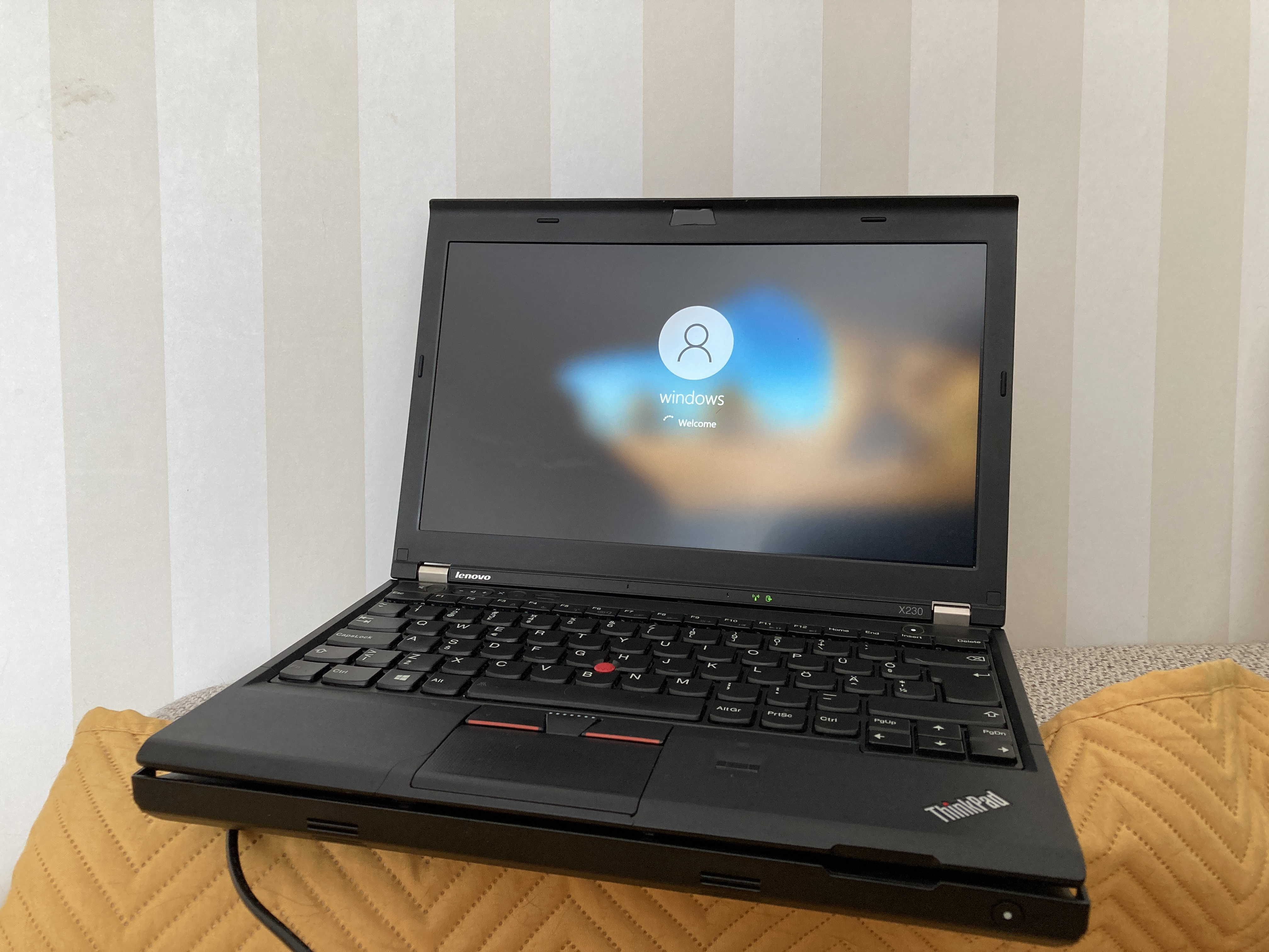
Windows 10 installed fine on the machine and while some functions don’t work as well (TrackPoint and touchpad being the prime examples here), it was still usable. Unfortunately I did not manage to write down the original Windows 10 key that is embedded to the stock BIOS image, so I could not activate it. But hey, at least it works.
Lessons learned
Even though this adventure started with a self-inflicted wound, I still consider it a success, as I learned a couple of things.
- It’s very easy to get confused when reviewing how the wires should be set up on the SOIC test clip and the device that’s actually performing the flashing.
- If a piece of software exposes a bunch of knobs and levers and warns you about catastrophic failures that might occur as a result, then trust it and don’t mess with things that you have no clue about. With this example case, though, I didn’t expect a memory speed change to result in such a catastrophic failure in the first place…
- Developers that know hardware are worth their weight in gold.
- Access to schematics is very valuable when fixing hardware.
And on the final note, I would like to give a shout-out to Arti Zirk, the guy who helped fix the mess I created. If you need someone who is well-versed in anything related to software development, Linux and embedded systems, then he is your guy.
flashrom references
This section has some commands that might be useful to you. Unless you’re using the exact same flasher, you will probably
need to specify a different programmer with the -p flag.
The names and extensions for the input-output files are arbitrary. A file is a file.
Reading/writing the top chip.
Note that I had to specify the chip type, otherwise flashrom would complain.
The top chip is 4MB and the bottom chip is 8MB. This should also be reflected in any output that you get.
--verify option is also useful for checking if the results are OK. I also recommend reading the image from the chip
after a write and comparing its checksum using md5sum, just to be extra safe.
# Read the existing image on the chip
flashrom -p ft2232_spi:type=2232H,port=B,divisor=4 -r top.bin -c MX25L3206E/MX25L3208E

# Write the specified image to the chip
flashrom -p ft2232_spi:type=2232H,port=B,divisor=4 -w top_backup.bin -c MX25L3206E/MX25L3208E
Reading/writing the bottom chip
# Read
flashrom -p ft2232_spi:type=2232H,port=B,divisor=4 -r bottom.bin -c MX25L6406E/MX25L6408E

# Write
flashrom -p ft2232_spi:type=2232H,port=B,divisor=4 -w bottom_backup.bin -c MX25L6406E/MX25L6408E
Subscribe to new posts via the RSS feed.
Not sure what RSS is, or how to get started? Check this guide!
You can reach me via e-mail or LinkedIn.
If you liked this post, consider sharing it!